
This post contains instructions on how to create your own Frequency Modulation Synthesizer using only simple and cheap components.
If you want to learn piano, check out earjoy.org
This project revolves around the Arduino Nano Board which can be picked up for around £2. This is a great project for beginers to delve into the world of electronic music device creation. If you are looking to learn how to build your own synthesizer, you have found the right place!
Here is a demonstration video of the synthesizer in action!
Components Required:
– Arduino Nano Board
– Audio Socket (1/4″ or 1/8″, I prefer 1/4″)
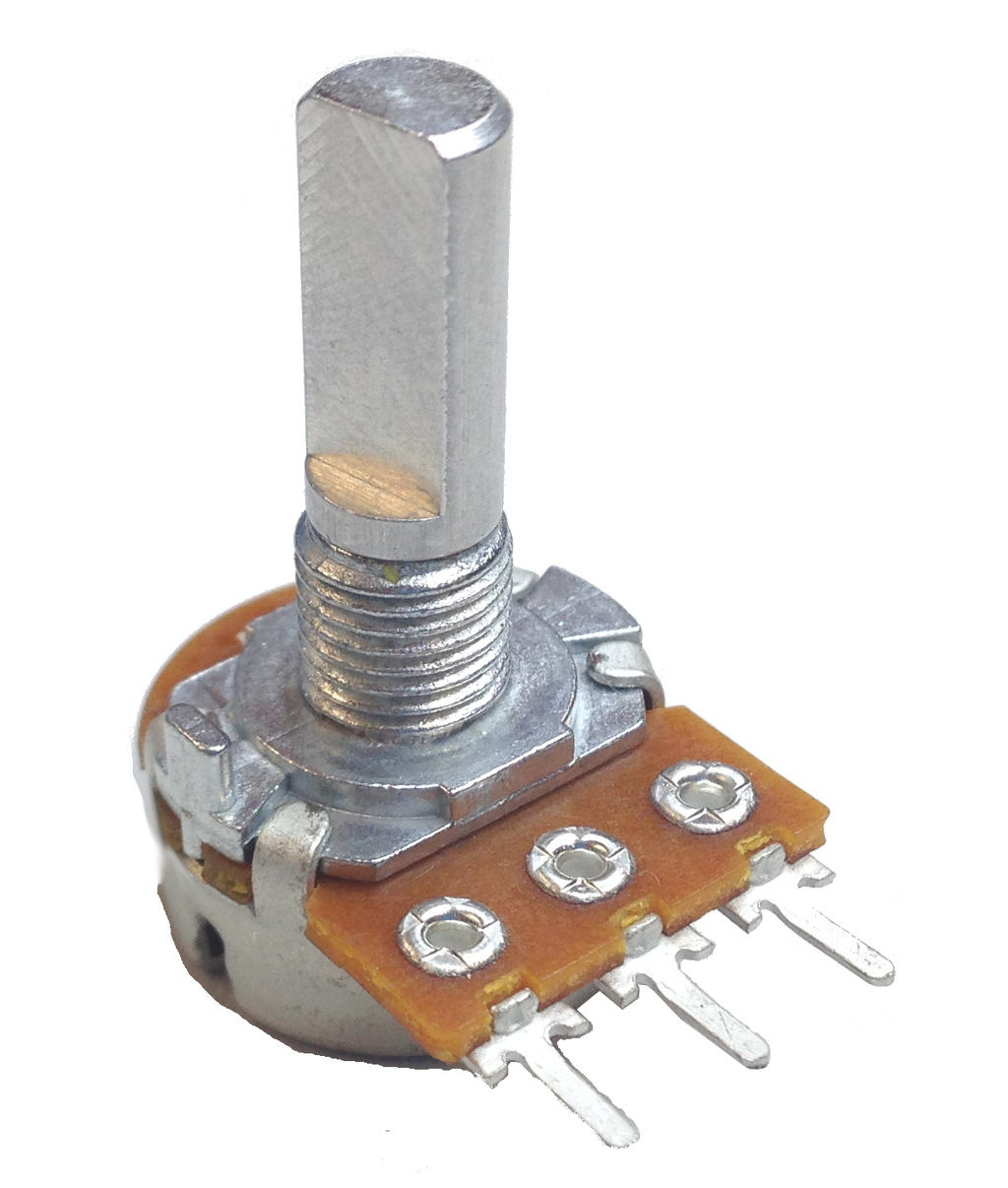
– 5x Potentiometer (doesn’t matter too much what the resistance value is, they might all need to match 100k is good)
– Stripboard
– Micro USB Cable (different arduinos use different cables – check!)
– Solder & Soldering Iron
– Electric Wire
– Some Kind of Speaker/ music system
– Additional: Breadboard, Light Variable Resistor, Case/Housing


Preparation:
1 – Acquire Materials
2 – Prepare Workspace (soldering iron, test speakers/audio interface)
3 – Install Arduino IDE Software + Mozzi Libraries on your computer (Install Guide: here)
Simplified Instructions:
1. Solder Potentiometers & Audio Socket to Arduino Nano
2. Upload Code to your Arduino (How To Guide)
3. Test It
4. Put in case
Detailed Instructions
1. Solder:
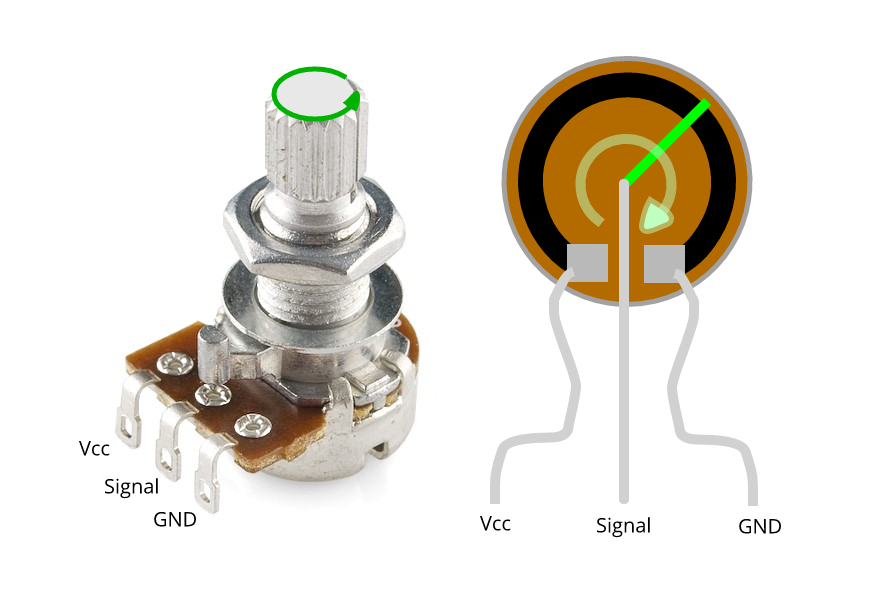
Solder the middle leg of each potentiometer to it’s own analog input on the arduino board (A0-A7). Connect the left leg to power (marked as 5V), and connect the right leg to ground. (it doesnt matter too much which side they go to, but it affects which way the knob is turned).
2. Then soldier the audio connector, hot terminal to arduino digital pin 9 (D9), cold terminalo to arduino ground.
I find it easiest to solder all the wires to the potentiometers first, then attach the wires to the arduino board. You can use a breadboard at this stage to test it out, or you will need to solder your arduino to some stripboard.

You should hopefully have something that looks like this:
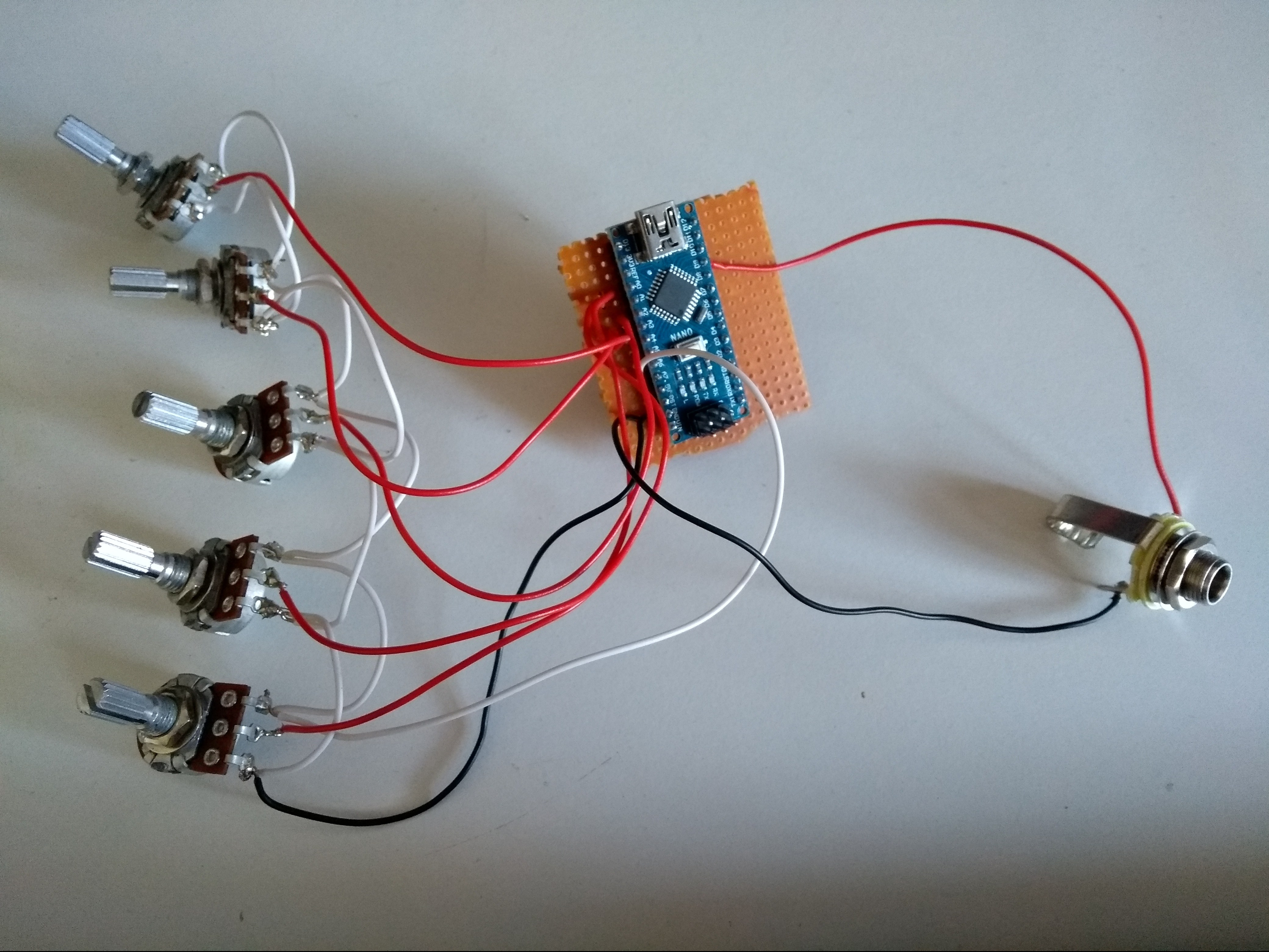
Note: you will need to make sure legs of the arduino are not connected. This might be ok depending on the stripboard you have, but I had to drill out the strips that connected the legs.

3. Uploading Code:
The next step is to upload the code (aka “sketch”) to the arduino board.
After you have installed Arduino IDE Software + Mozzi Libraries, Open the Arduino IDE Software, and connect your arduino to your computer. Ensure you have selected the correct board and port on the software (MORE INFO HERE).
CODE: The code we will be using in this case is an adaptation of a Mozzi Example Code. Delete all the text in the arduino code box and copy and paste the code FROM THIS LINK – CLICK HERE FOR CODE.
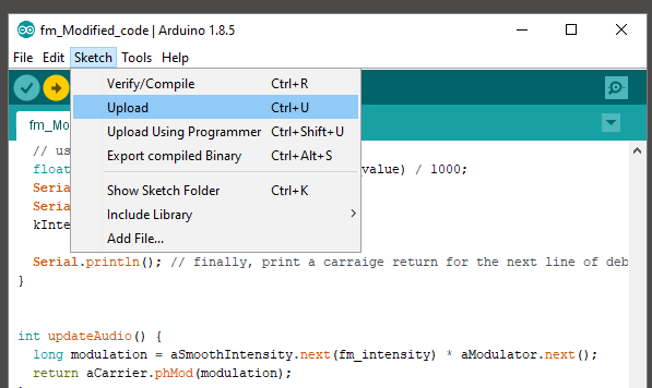
Once you have pasted the code, and ensured in the “Tools” menu you have the correct “board” and “port” settings,
click “Sketch>Upload”
the lights on the board should flash and you will eventualy recieve an upload complete message!
4. Your synth should now be ready to start making noises!
The arduino nano board will be powered by the USB cable so all thats left to do now is to plug it into your speakers or audio interface and start going crazy…
after this you can mount the circuit and potentiometers in a case, this can be anything, a tin etc. then you can stick some knobs on it.
Send in photos of your synth creation or comment for advice!
If you’re looking for the best places to download free samples, check out earjoy.org
Sign up to the ark audio mailing list to get updates on the latest tutorials, free downloads, deals and music info!

Have you installed the mozzi library?
LikeLike
Yes, I have installed the Mozzi library. I added to to Arduino IDE using the “Add Zip File” function.
I can install some of the Mozzi examples fine, but your text throws up lots of errors.
I think there are characters missing in the text that the link points to.
I’m really keen to do this project as I think it would be the start of more audio hardware experiments.
LikeLike
https://arkaudio.co.uk/2018/12/16/the-impact-of-increased-accessibility-in-music-technology/
The code is also at the bottom of this article, might work!
LikeLike
I know next to nothing about coding, but there seems to be all sorts of characters missing in the linked code in the article compared to the other one you linked to (thanks for that link, it worked a treat). I managed to get this to work on my arduino nano
#include
#include // oscillator
#include // table for Oscils to play
#include
#include // maps unpredictable inputs to a range
// int freqVal;
// desired carrier frequency max and min, for AutoMap
const int MIN_CARRIER_FREQ = 22;
const int MAX_CARRIER_FREQ = 440;
const int MIN = 1;
const int MAX = 10;
const int MIN_2 = 1;
const int MAX_2 = 15;
// desired intensity max and min, for AutoMap, note they’re inverted for reverse dynamics
const int MIN_INTENSITY = 700;
const int MAX_INTENSITY = 10;
// desired mod speed max and min, for AutoMap, note they’re inverted for reverse dynamics
const int MIN_MOD_SPEED = 10000;
const int MAX_MOD_SPEED = 1;
AutoMap kMapCarrierFreq(0, 1023, MIN_CARRIER_FREQ, MAX_CARRIER_FREQ);
AutoMap kMapIntensity(0, 1023, MIN_INTENSITY, MAX_INTENSITY);
AutoMap kMapModSpeed(0, 1023, MIN_MOD_SPEED, MAX_MOD_SPEED);
AutoMap mapThis(0, 1023, MIN, MAX);
AutoMap mapThisToo(0, 1023, MIN_2, MAX_2);
const int KNOB_PIN = 0; // set the input for the knob to analog pin 0
const int LDR1_PIN = 1; // set the analog input for fm_intensity to pin 1
const int LDR2_PIN = 2; // set the analog input for mod rate to pin 2
const int LDR3_PIN = 4; // option for additional control sources
const int LDR4_PIN = 3; // further control source
Oscil aCarrier(COS2048_DATA);
Oscil aModulator(COS2048_DATA);
Oscil kIntensityMod(COS2048_DATA);
int mod_ratio = 5; // brightness (harmonics)
long fm_intensity; // carries control info from updateControl to updateAudio
// smoothing for intensity to remove clicks on transitions
float smoothness = 0.95f;
Smooth aSmoothIntensity(smoothness);
void setup() {
Serial.begin(115200); // set up the Serial output so we can look at the light level
startMozzi(); // :))
}
void updateControl() {
// freqVal = map(LDR3_PIN, 0, 1023, 1, 100);
int freqVal = mozziAnalogRead(LDR3_PIN); // value is 0-1023
int FRQ = mapThis(freqVal);
int knob2 = mozziAnalogRead(LDR4_PIN); // value is 0-1023
int knob2Val = mapThis(knob2);
// read the knob
int knob_value = mozziAnalogRead(KNOB_PIN); // value is 0-1023
// map the knob to carrier frequency
int carrier_freq = kMapCarrierFreq(knob_value);
//calculate the modulation frequency to stay in ratio
int mod_freq = carrier_freq * mod_ratio * FRQ;
// set the FM oscillator frequencies
aCarrier.setFreq(carrier_freq);
aModulator.setFreq(mod_freq);
// read the light dependent resistor on the width Analog input pin
int LDR1_value = mozziAnalogRead(LDR1_PIN); // value is 0-1023
// print the value to the Serial monitor for debugging
Serial.print(“LDR1 = “);
Serial.print(LDR1_value);
Serial.print(“\t”); // prints a tab
int LDR1_calibrated = kMapIntensity(LDR1_value);
Serial.print(“LDR1_calibrated = “);
Serial.print(LDR1_calibrated);
Serial.print(“\t”); // prints a tab
// calculate the fm_intensity
fm_intensity = ((long)LDR1_calibrated * knob2Val * (kIntensityMod.next() + 128)) >> 8; // shift back to range after 8 bit multiply
Serial.print(“fm_intensity = “);
Serial.print(fm_intensity);
Serial.print(“\t”); // prints a tab
// read the light dependent resistor on the speed Analog input pin
int LDR2_value = mozziAnalogRead(LDR2_PIN); // value is 0-1023
Serial.print(“LDR2 = “);
Serial.print(LDR2_value);
Serial.print(“\t”); // prints a tab
// use a float here for low frequencies
float mod_speed = (float)kMapModSpeed(LDR2_value) / 1000;
Serial.print(” mod_speed = “);
Serial.print(mod_speed);
kIntensityMod.setFreq(mod_speed);
Serial.println();
}
int updateAudio() {
long modulation = aSmoothIntensity.next(fm_intensity) * aModulator.next();
return aCarrier.phMod(modulation);
}
void loop() {
audioHook();
}
LikeLike
This code does not compile for me. The linked code in the article doesn’t work either.
LikeLike
I can get sound of of it, but the signal is VERY quiet, so when I plug it into a mixer (like a guitar) its really noisy and sounds awful. I presume I need some sort of amplifier circuit. Do you have any advice on that? Thanks
LikeLike
Hi Richard, I’m glad you got it working! Hmm, mine doesn’t have that problem, it is fairly loud and I havent amplified it, you could try the LM386 amplifier circuit listed on this article!
https://arkaudio.co.uk/2019/02/12/synth-companies-hate-him-i-swapped-my-moog-for-a-soldering-iron-and-why-you-should-do-the-same-part-1/
http://www.circuitbasics.com/build-a-great-sounding-audio-amplifier-with-bass-boost-from-the-lm386/
are you powering your board with USB?
LikeLike
It is powered by USB, either a battery pack or into a powered USB hub.
I’m using a mono cable to connect the audio jack to the mixer, but have the turn that up very loud to hear it, so it ends up really noisy
I have ordered an amplifier board to see if that helps, along with some new 100k potentiometers
LikeLike
Looks like an interesting project,
A few questions/requests
1. I noticed that there are 8 analogue inputs but only 5 pots, which of the analugue input are connected to potentiometers?
2. Should I use linear or log potentiometers?
3. Where is the LDR connected?
4. Any chance of adding a circuit diagram?
LikeLike
Hello! Sorry for the late response. You need to use analogue pins A0-A4. This could be expanded with more code.
2. You can use either type of potentiometer, linear working better for some parameters.
3. One leg to GND, one to +5v seperated by a less than 1k resistor. The power leg also goes to an analogue pin
LikeLike
4. Maybe soon
LikeLike
Hi, I’m really stuck with uploading the code. Apparently these Chinese Nano’s need an older version of bootloader? I’ve built it and that’s as far as I can get.
James
LikeLike
Hi James, I think you need to sellect Board>ATMega(Old bootloaded) In the ‘Tools’ Menu. I’ve had this issue befoer but that should fix it
LikeLike
Hi noahfk, thanks very much for that and I’ll pass that onto my friend who say’s he’s corrected the code needed and see what he think’s. Keep you posted. If you want to email me I can send you a picture of the build so far.
LikeLike
If anyone is getting /342 errors, it’s due to unicode characters in the copy/paste of the code. Replace all of the ” and it will compile. Literally delete the ” and retype it.
LikeLike